How to check MRI safety and MRI implant safety? This question is not straightforward unless use of full non-magnetic electric field probe. However this latter condition is necessary but not sufficient. Indeed, the effective permittivity of the non-magnetic electric field probe should also match the one of the gelled saline MRI phantom. Lastly, no artifact should be induced by the non-magnetic electric field probe on the MRI images. Kapteos non-magnetic electric field probes fulfill all these conditions, whatever the static magnetic field (0.55T to 7T) of the MRI machine.
The following results have been carried out on a 7T Bruker MRI machine at Creatis laboratory in France with a non-magnetic electric field probe eoProbe™ ET1-bio presenting a 1-mm spatial resolution.
Checking artifact-free behavior of the non-magnetic electric field probe
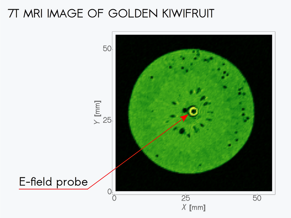
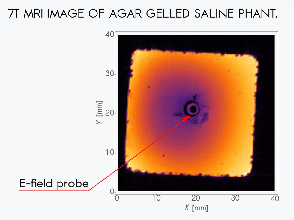
The artifact-free behavior of Kapteos bio-line probes on the MRI images have been already validated several years ago for MRI machines up to 4.7T. We present here first results on a 7T MRI machine. For that purpose, two MRI images (256 x 256 pixels) have been taken:
the first one concerning a golden kiwifruit,
the second one concerning an agar gelled saline phantom.

The probe appears as a black disk surrounded by a white crown, surrounded itself by a black crown. From the center to the probe edge, these three elements correspond to:
the 1.75-mm diameter electro-optic crystal acting as the non-magnetic electric field probe transducer,
the gel filling the gap between the transducer and the probe sheath,
the high permittivity probe sheath and some air cavity created by the probe insertion.

With agar gelled saline phantom, the probe insertion inside the phantom has led to cracks in the phantom that are clearly visible on the image. Apart these mechanical damages, no image artifact is caused by the non-magnetic electric field probe itself.
Permittivity matching of the non-magnetic electric field probe
From the international standard IEC 62209-2, a human-tissue simulating phantom should present a permittivity with a value of 45.3 for its real part at 300 MHz (7T MRI). Kapteos non-magnetic electric field probes for biological applications are composed of a high permittivity sheath (εr ≅ 23) and a high permittivity transducer (εr ≅ 48), thus leading to a very good permittivity matching with the phantom.
This constitutes a key point as the E-field distribution in a phantom can be strongly modified, both in magnitude and direction, when an element is inserted. This occurs when the permittivity of the inserted element presents a high ratio relative to the phantom permittivity. The permittivity ratio is defined by relation η = max{εelt/εphant, εphant/εelt} and should remains close to 1. This is the origin of MRI implant safety issue as the E-field enhancement is directly linked to η.
With a Kapteos non-magnetic electric field probe which effective permittivity is 30 ± 4, this permittivity ratio presents a value of only 1.5, far from an air inclusion for which η = 45.3! With metallic elements, the situation is even worse.
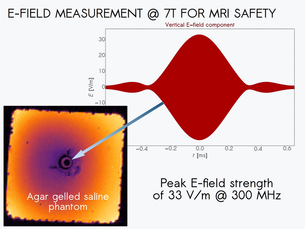
E-field measurement @ 7T with a non-magnetic electric field probe
Two measurements have been carried out in an agar gelled saline phantom @ 7T:
the first one concerning the temporal profile of the carrier envelope,
the second one concerning the record of the carrier at center of MRI pulse.
On the 7T Bruker MRI machine, the E-field components measured inside the agar gelled saline phantom are much lower the the ones encountered on 3T clinical MRI machines. Indeed, the maximum E-field strength is only 24 Vrms/m. The longitudinal component of the E field, below the noise floor (0.6 Vrms/m), is not represented.
The time evolution of the carrier at center of MRI pulse is fitted by a continuous wave from which we get:
the carrier frequency of 300.30 ± 0.04 MHz,
the carrier phase of 31 ± 0.4°,
the carrier magnitude of 550 ± 4 µV.
The histogram of the residue (difference between measurement and theoretical fit) is also given. It presents a Gaussian shape with a standard deviation of 63 µV, representative of a white noise. For such noise distribution, signal processing is straightforward as a simple average of a large number (N) of samples leads to an increase of the signal-to-noise ratio as √N.
Courtesy of Creatis Lab. (Paul Nobre)
Key features of the Non-Magnetic Electric Field Probe for MRI safety and MRI implant safety
single probe to cover all existing and future MRI machines: 23.4MHz (0.55T) → 500MHz (11.7T)
ultra high orthogonal E field components rejection ratio: > 50 dB
ultra high spatial resolution: < 1 mm
high measurement reproducibility: 0.15 dB
ultra compact non-magnetic electric field probe: ∅ = 4 mm
full dielectric, high permittivity, non-magnetic electric field probe: εr ≅ 30
high sensitivity: 0.6 Vrms/m noise floor
ultra high dynamic range: 120 dB
For more information, fell free to contact us.


Comments